Does structure matter to how a framework is understood and used?

Back in October 2014, John Reilly, a Subject Matter Expert and Distinguished Fellow with the TM Forum published a piece on LinkedIn[1] about the future of the Business Process Framework (more commonly known as the enhanced Telecom Operations Map (eTOM)) that is published by the TM Forum. His proposals are based around a domain based structure making the eTOM more closely aligned with the structure of the Information Framework (aka SID) and the Technical Application Framework (aka TAM). This re-structuring has addressed some of the issues that are apparent with the eTOM and its relationship with the other frameworks that make up the Frameworx document set.

The evolution of the Business Process Framework

But firstly a bit of history about the development of the eTOM, its previous incarnation the TOM and the SID.
The Telecom Operations Map (TOM), itself based upon the ITU-T Telecommunications Management Network (TMN) model and earlier work done by the TMForum, was proposed in the late 1990s and looked at defining the key processes required by a Telecommunications Company to manage its operations.

Microsoft Word - GB910 TOM 2.0 Nov 1999.docTelecom Operations Map ©TM Forum

As can be seen, the TOM copied the management layers defined in the TMN standard. The document (GB910) which set out the TOM also described end to end processes based upon Fulfilment, Assurance and Billing which could be overlaid onto the TOM model.

Microsoft Word - GB910 TOM 2.0 Nov 1999.docTOM ‘FAB’ End-to-End Process Breakdown ©TM Forum

The structure of the TOM model not just implied, but made explicit, how process flows ‘worked’ from a Customer placing an order to the Services being planned and the Network being configured to deliver that particular order. This became the basis of how process flows using the TOM were modelled.
The TOM evolved into the eTOM over the next couple of years, becoming a total enterprise process framework, encompassing all the processes needed by an organisation. The basic structure of the framework, vertical process groupings and the associated end-to-end flows, was not altered; though more were added. This caused some confusion, particularly with the introduction of the Supplier/Partner processes as many looking at the model, and familiar with the end-to-end process flows that had been defined in the TOM, assumed that processes needed to flow though all management layers from Customer to Supplier/Partner.

eTOMv1eTOM v1 ©TM Forum

The eTOM continued to evolve with much of its development focused upon the decomposition and definition of lower level processes but the overall structure of the framework changed relatively little over the next decade.

 eTOM 8eTOM Level 0 Processes, Release 8 © TMForum

 Development of the SID

The principles of what was to become the Shared Information/Data Model (SID) were first proposed in 1999. Initially two separate development strands: The Shared Integration Map (SIM) and the Shared Information/Data Model: ran together within the TMForum. The SIM[2] proposed a number of different management domains and defined, to some, degree how they were related to the TOM processes.

Systems Integration MapSIM Management Domains © TMForum

Systems Integration MapPrimary Mapping Between the Management Domain Concept and the TOM ©TMForum

The eTOM and SID continued to be developed separately, for a number of years, as each fulfilled a different requirement for the TM Forum members and their respective roles within, what was, the NGOSS lifecycle. A mapping between the SID ABEs and the eTOM level 2 processes[3] allowed process modellers to more easily to use the SID to enrich their process flows while using the same constructs as system developers and integrators.
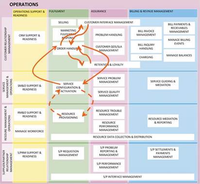
The issues with structure of the eTOM remain and recent developments, as discussed in John Reilly’s blog, have been more focused upon the addressing alignment between the SID and eTOM. These changes haven’t removed one of the key advantages of the eTOM, in that is very easy to construct initial process flows using the model; as illustrated in the figure below.

030314_1558_StaticandDy3.jpgInitial Process Flow Constructed Using the eTOM

While the recent changes to the eTOM have been a good way forward but they do not address some of the fundamental issues of the structure of the eTOM, for example:

  • How Customer and Supplier/Partner interact with the vertical and horizontal processes groupings.
  • The relationship between vertical process flows and horizontal functional groupings
  • The relationship between the eTOM and the SID.
  • How Enterprise Management works with the Operations and SIP Process Areas.

Is there another way of viewing a process framework?

When ITIL® was refreshed in 2007 it introduced a fundamental change in how the framework was visualised and published a view of the framework which illustrated the Service Management Lifecycle and the relationship of the five key process areas.

030314_1558_StaticandDy1.jpgITIL v3 Service Management Lifecycle

Similarly COBIT and TOGAF have lifecycle models which define the relationship between process areas from which process flows can be derived.

So is there are better way of laying out the eTOM?

Does the structure of the eTOM need to change, so member organisations, particularly new members and other industries, immediately understand how the eTOM can benefit them to meet the challenges they are facing not just now, but in the future? It is clear that what has been developed so far should not be wholly discarded; this paper is concerned with how the L0 and L1 process groupings, and possibly the L2 processes, are presented and what makes up those groupings. The issues with the eTOM structure that were described earlier can be, for the most part, condensed to one key issue – there is no clear process lifecycle throughout the framework; the process and external relationships implied by the layout of the eTOM can make the framework difficult to understand initially. And where lifecycles have been defined, e.g. Infrastructure Lifecycle Management and Product Lifecycle Management, the relationship between them and other areas of the eTOM is poorly described.
So what is proposed is that level 0 and level 1 groupings and relationship be redefined. Key to these changes to the eTOM structure would be the definition of the various lifecycles (i.e. Product Lifecycle, Infrastructure Lifecycle, Customer Lifecycle, Supply Chain Lifecycle etc) that exist within the framework as well as the inter-lifecycles (for example Fulfilment, Assurance and Billing with the Customer Lifecycle.) Defining the lifecycles would provide an opportunity for closer alignment between the level 1 process groupings (which would themselves become lifecycle groupings in this proposed new framework structure) and the relevant SID domains. Once these have been described, then the relationships between the different lifecycles can be established and the framework’s new structure derived. This would allow the relationships between the lifecycles and the internal and external stakeholders to be more clearly illustrated.
Caution should be taken, in that any re-design of the structure of the framework must maintain one of the principle benefits of the current layout; the ease by which initial process flow can be constructed.
This is not a simple task, but there is an opportunity to look at the eTOM and see how it could be redesigned to support the digital transformation that is affecting all industries.

[1] https://www.linkedin.com/pulse/20141029152421-7101265-the-future-business-process-framework-etom?trk=object-title
[2] GB914 System Integration Map
[3] GB922 Concepts and Principles

Posted in Process Modelling | Tagged , , , | 1 Comment

Static and Dynamic Modelling

The concept of creating a process flow using a process map or framework is not a new concept; in fact it is generally how processes flows are created today and have been for some time.

So what have I to say about a methodology that is standard practice?

To start with, let’s define what I mean by static and dynamic models. A static model is one that describes a number or processes and the generalised relationship between them; for example the ITIL® Service Management Framework (fig 1) or the Business Process Framework (aka eTOM) published by the TM Forum (fig 2).

fig 1: ITIL® Service Lifecycle – showing process groupings

fig 2: Business Process Framework – showing Level 1 relationships

Neither of these models set out the order that the processes within them should be joined. While both frameworks have exemplar process flows; these are more for illustration that a prescribed way the processes flows have to work. Static models are always generic, not all organisations will use all the elements within a framework model and there will be instances where new or enhanced/modified elements are required for an organisation. Static models cannot be implemented.

A dynamic model, more generally called a process flow, is where processes are connected together to achieve a particular objective. Dynamic models are, by their nature, specific to an organisation or implementation as the process flow will capture the data/information used by a process within the flow, the application or person which undertakes the process activity and the process owner. As I have said, exemplar process have been developed but these will always need to be adapted for an organisation and do not go into the detail required for implementation.

Static models are used to create dynamic models.

In the last decade there has been a lot of work in linking or showing the relationship between difference frameworks; either describing the relationship between a process framework and data/information model or between different industry frameworks. This has led to a number of tables and matrices that try to explain the relationships between frameworks; for example the TM Forum publication ‘GB922 Concepts and Principles’ which defines the relationship between the Business Process Framework and the Information Framework (aka SID) or the ISACA publication which defines a mapping between COBIT and ITIL.

While these publications allow modellers to quickly develop dynamic models with the correct data/information element associated with the right process etc, these flows are idealised; there is always ambiguity within mapping between static models. What I mean by ambiguity, is it that a one to one relationship between the elements within each static framework cannot be defined.

The relationship between two static models is, at worst many to many or at best, one to many; for example in ‘GB922 Concepts and Principles’ an Information Framework Aggregated Business Entity (ABE) is mapped to several Business Process Framework Level 2 processes. In this case while the process identified as the primary process may create, read, update and delete the ABE, many other processes may need to read and/or update the ABE in order to undertake their function. Other reasons for this ambiguity include:

  • The abstraction level of the framework used when defining a mapping. The higher the level of abstraction the greater the ambiguity and the increasing likelihood that the mapping will be many to many.
  • Different framework use different levels of abstraction. What is defined as a level 1 process in one framework may not correlate to a level 1 process in another creating process scope overlap and a many to many mapping.

So how is this ambiguity resolved?

As I have said static models are generic, therefore any mapping between static models will always have ambiguity within it. Mapping at a lower level of abstraction is more likely to produce a one to many mapping thus reducing some of the ambiguity but this work is difficult and time consuming. Also dynamic models are specific to an organisation and their implementation and it is the specific nature of the dynamic model which eliminates the ambiguity that is present in the static model. To achieve this it is good practice, when developing a process flow, to define the following:

  • Pre-conditions/assumptions
  • Post-conditions
  • A clearly defined start and end
  • Process flow goal/purpose
  • Process owner

What this does is define the overall context of a process flow so that a specific, one to one, mapping between static models can be realised.

So far, so good and nothing tremendously new or controversial in what I have said…except the context of a process flow can be different for the same process flow.

What? you may ask.

If we take a simple process flow (fig 3), it can be seen that this process flow fulfils a number of contexts; for example:

  • A new customer ordering new services
  • A current customer changing delivered services
  • A current customer cancelling their services


fig 3: A Simple Process Flow

Each of these contexts have a different outcome and use different data/information at different steps and in different ways; the first example creates a customer record and the last deletes it. What this does demonstrate is one of the cornerstone benefits of standardising processes and that is maximising process re-use.

The second issue is, as I have already said, that the static model is generic and therefore, not all organisations will use all the elements within a framework model and there will be instances where new or enhanced/modified elements are required for an organisation. This means that when mapping between static models not all the permutations and combinations of the model relationship will be captured. This is partly to stop the mapping from becoming too large and unwieldy and also because, using a process framework as an example, all the possible process flows have not been modelled.

What does this mean for the static model mapping?

I am not saying that any mapping that exists is useless and should be discarded; for example in identifying what data is used within a process flow to achieve its objective a mapping between a process framework and information framework provides an excellent starting point and ensures consistency between the frameworks. And that is the key point, it’s a starting point, it is not the complete story and if the processes flow needs to use data/information in a different way to a mapping do not automatically assume that the process flow is wrong. Additionally the dynamic model should always not have any ambiguity within it otherwise it cannot be implemented. This means that a one to one mapping between the static models used in the development of the process flow must be realised in the dynamic model.

Posted in Uncategorized | Leave a comment

How Cloud Services got me thinking about a falling tree and a boxed cat

If we use the internet we are inevitably using Cloud Services somewhere; be it Gmail, Facebook or Dropbox. But a question from a colleague got me thinking about the availability of such Services and, even, if they are really are a Service.

It was George Berkley in his book ‘A Treatise Concerning the Principles of Human Knowledge’ who gave us the seed to what was to become the question:

‘If a tree falls in a wood and there is no creature is around, does it make a sound?’

This is a fundamental question about the nature of existence – can something exist without being perceived? Does a sound exist if there is no one, or no creature, there to hear it? Albert Einstein is reported to have asked his fellow physicist and friend Niels Bohr whether he realistically believed that ‘the moon does not exist if nobody is looking at it.’ To this Bohr replied that however hard he (Einstein) may try, he would not be able to prove that it does, thus giving the entire riddle the status of a kind of an infallible conjecture – one that cannot be either proved or disproved[1].

So, what does this have to do with Cloud Services?  I was once asked by a colleague about how Cloud Services and their associated performance metrics could be modelled and, consequently, how its availability is calculated. This got me thinking about what a Cloud Service really is and I suggested, at the time, that a Cloud Service may not even be a Service if is not being used.  This goes straight back to the tree in the unoccupied wood and we can pose a very similar question about Cloud Services:

‘Does a Cloud Service exist as a Service if no one is using it?’

We should note, at this point, how Cloud Services differ from traditional telephone or IT (Client-Server) Services. While you may not use the telephone all the time the dial tone is always present (unless it has gone wrong) as you are always and physically connected to the exchange. Similarly with IT Services in an office environment, you are, generally, always connected to the Server on which data may be stored and shared. A connection is not established only when you try and retrieve or save data to the server. Cloud Services differ in that you do not have a persistent connection with the Service unless it is being used.

To look at it another way a Service is defined in the ITIL Glossary[2] as:

‘A means of delivering value to customers by facilitating outcomes customers
want to achieve without the ownership of specific cost and risks.’

It is clear that Cloud Services meet this definition when being used, but it is equally clear there is no value being delivered to the customer if they are not using the Service. So if no value can be placed on a Cloud Service that is not being used, how should a Service Provider price such a Service for Customers? It can be argued that there is a tangible value to a Cloud Service not being used as it is always ready to be used. But can this be called a Service?

This got me thinking further; how do we calculate the availability of a Cloud Service if there is no persistent connection or any value to the customer if they are not using it? Or if the Cloud Service cannot be said to exist as a Service when it is not being used what is its availability? If a user uses a Cloud Service for the same two hours every week throughout the year, what is its availability? Is it 100% because they never have a problem using it when they needed it or is it 1% because the other 8655.7 hours during the year the Service was not used may or may not have been available during that time? And if the user tries and use this Service outside the hours they normally use it and it works how does this affect the availability calculation? What if it doesn’t work (ignoring scheduled downtime which many Service Providers and System Builders remove from their availability calculations)? It was thinking about this muddle that I remembered the cat in the box.

In 1935 Erwin Schrödinger proposed a Gedankenexperiment, or thought experiment, in which a cat is placed in a sealed box and the cat’s life or death is depended upon the state of a subatomic particle. According to Schrödinger, the Copenhagen interpretation[3] of quantum mechanics implies that the cat remains both alive and dead (to the universe outside the box) until the box is opened. Extrapolating this for Cloud Services the following conjecture can be put forward:

‘A Cloud Service is both available and unavailable until the point it is used. ‘

This raise yet another issue: at what point does the Cloud Service start? When a user makes a connection to the Cloud or when the user actually has access their data stored in the Cloud? But I digress slightly.

The conjecture that I have put forward does raise some interesting questions, particularly about calculating a Cloud Service’s availability when it can be considered both available and unavailable at the same time when it is not being used.

So where does this lead us? Apart from some very philosophical thinking about Could Services it does raise some interesting questions about what exactly a Service is and how to measure its performance and define and report its availability.

Posted in Cloud Services, Service Availability, Service Management | Leave a comment